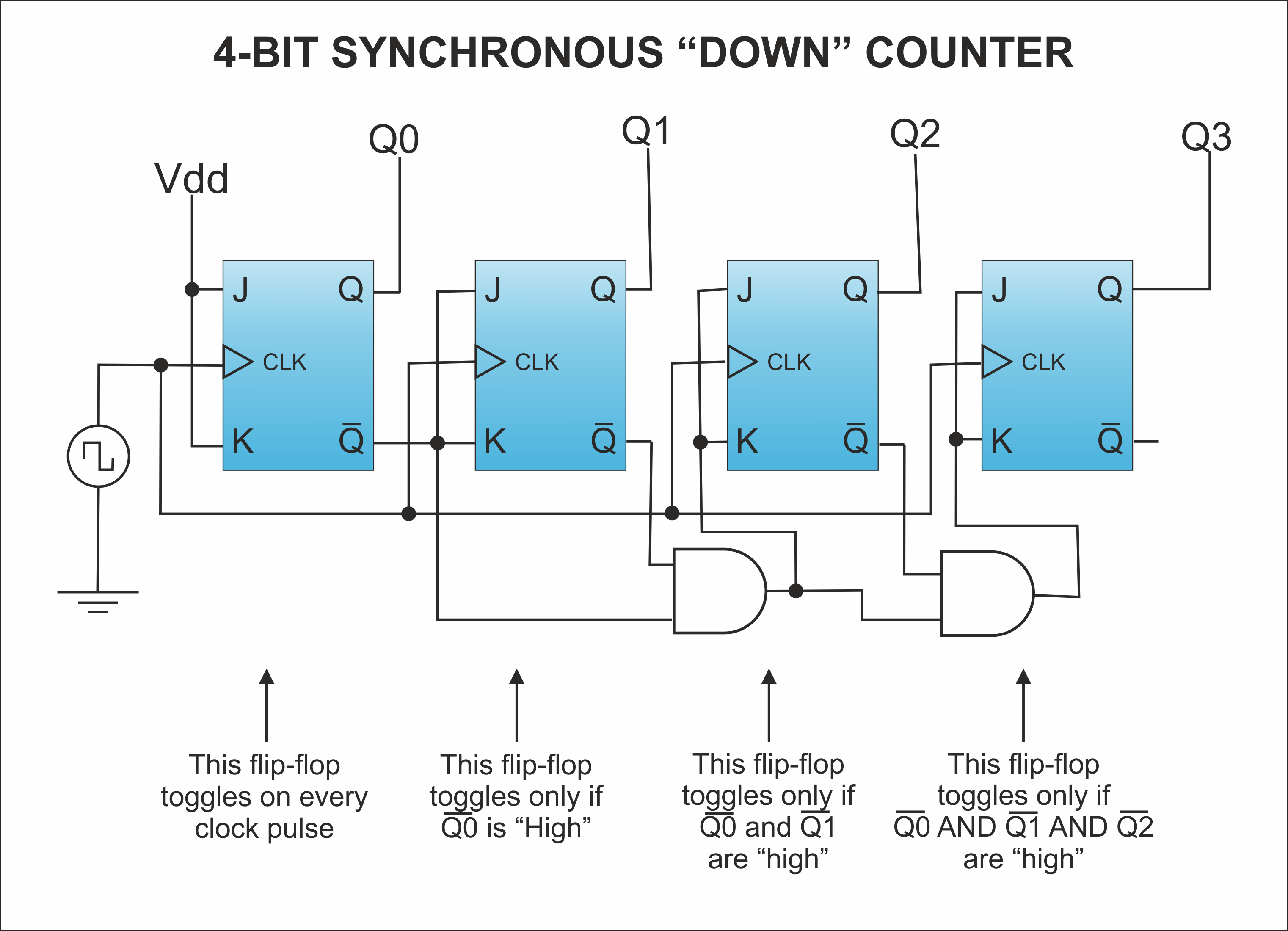

- 4 BIT DOWN COUNTER WITH EDGE TRIGGERED FLIP FLOP FULL
- 4 BIT DOWN COUNTER WITH EDGE TRIGGERED FLIP FLOP CODE
In the same manner, the Q B acts as clock for the third FF, therefore the output state (Q C) of the third FF will be toggled for every falling edge of Q B. Q B) will be toggled at every falling edge of Q A. As the Q A is feed as a clock to the second FF, therefore the output state (i.e. Q A) will be toggled at every falling edge of the clock pulse. Therefore, the output state of the first counter(i.e. The -ve edge clock pulse is provided to 1st counter. All the counter states are generated by the frequency division. the counter state transition can occur only at falling edge of the clock pulse), therefore toggling will take place. Here the -ve edge clock pulse is used(i.e. The working of counter can be easily understood by the timing diagrams. But the output(Q) is taken from each FF.īy both implementations, we can acquire the same counting states. Q’ B) of the second FF is feed as a clock for the third FF. Thereafter, the complemented output of the first FF(Q’ A) is feed as a clock to the second FF and complemented output(i.e. In this implementation, the clock pulse is given to only the first FF. same as Up counter but output states are complemented). But the complemented output is taken from each FF(i.e. Thereafter, the output of the first FF is feed as a clock to second FF and the output of the second FF is feed as the clock for the third FF. In this implementation, the clock pulse(of 50% duty cycle) is given to only the first FF. We can generate down counting states in an asynchronous down counter by two ways. For the 3 bit counter, we require 3 flip flops and we can generate 2 3 = 8 state and count(111 110 … 000). Please refer this, to understand how an asynchronous counter works. In the case of synchronous FFs, all the flip flops are triggered simultaneously by an external clock pulse. In the asynchronous counter, an external clock pulse is provided for only the first flip flop, thereafter the output of the 1st FF acts as a clock pulse for the second FF and so on. They are constructed with flip flops and logic gates. We can also say that counters are sequential circuits which change their pre-defined states with the help of clock pulses. They are used to measure the time and frequency. The clock pulses occur at regular intervals. Design 101 sequence detector (Mealy machine)Ĭounters are used to count the clock pulses. Flip-flop types, their Conversion and Applications. 4 BIT DOWN COUNTER WITH EDGE TRIGGERED FLIP FLOP CODE
Code Converters - BCD(8421) to/from Excess-3. Code Converters - Binary to/from Gray Code. Difference between combinational and sequential circuit. Difference between Unipolar, Polar and Bipolar Line Coding Schemes. 4 BIT DOWN COUNTER WITH EDGE TRIGGERED FLIP FLOP FULL
Difference between Half adder and full adder.IEEE Standard 754 Floating Point Numbers.Program for Binary To Decimal Conversion.Program for Decimal to Binary Conversion.ISRO CS Syllabus for Scientist/Engineer Exam.

ISRO CS Original Papers and Official Keys.GATE CS Original Papers and Official Keys.


 0 kommentar(er)
